RGB SCART adapter for 1084s
05/01/17
- need a 9-pin D-SUB plug + backshell
- need a female SCART plug
- wiring info (need to find SCART pin layout to confirm and double check the D-SUB one)
   The 9 pins on the 1084s D connection are:

               5 4 3 2 1
               | | | | |
              ___________
             ( o o o o o )
              \ o o o o /
               ---------
                | | | |
                9 8 7 6

   Pin 1 .......... Ground red
   Pin 2 .......... Ground green
   Pin 3 .......... Red video in
   Pin 4 .......... Green video in
   Pin 5 .......... Blue video in
   Pin 6 .......... Ground blue
   Pin 7 .......... Composite sync in
   Pin 8 .......... Horizontal sync
   Pin 9 .......... Vertical Sync

   Simply make the connections as follows:

                 .---------------------------------------------.
   Female SCART  |  7   |  11   |   15  |   16  |  18   |  20  |
   Wire colour   | blue | green |  red  | white | black |yellow|
   Male RGB      |  5   |   2   |   3   |    9  |   8   |   7  |
                 `---------------------------------------------'

   The resulting cable should look like this:

             _______             ______________
            ( 9 pin )-----------| 21 pin scart |
             \_____/------------|_______________\
06/01/17
- Ordered a male DB9 connector.
08/01/17
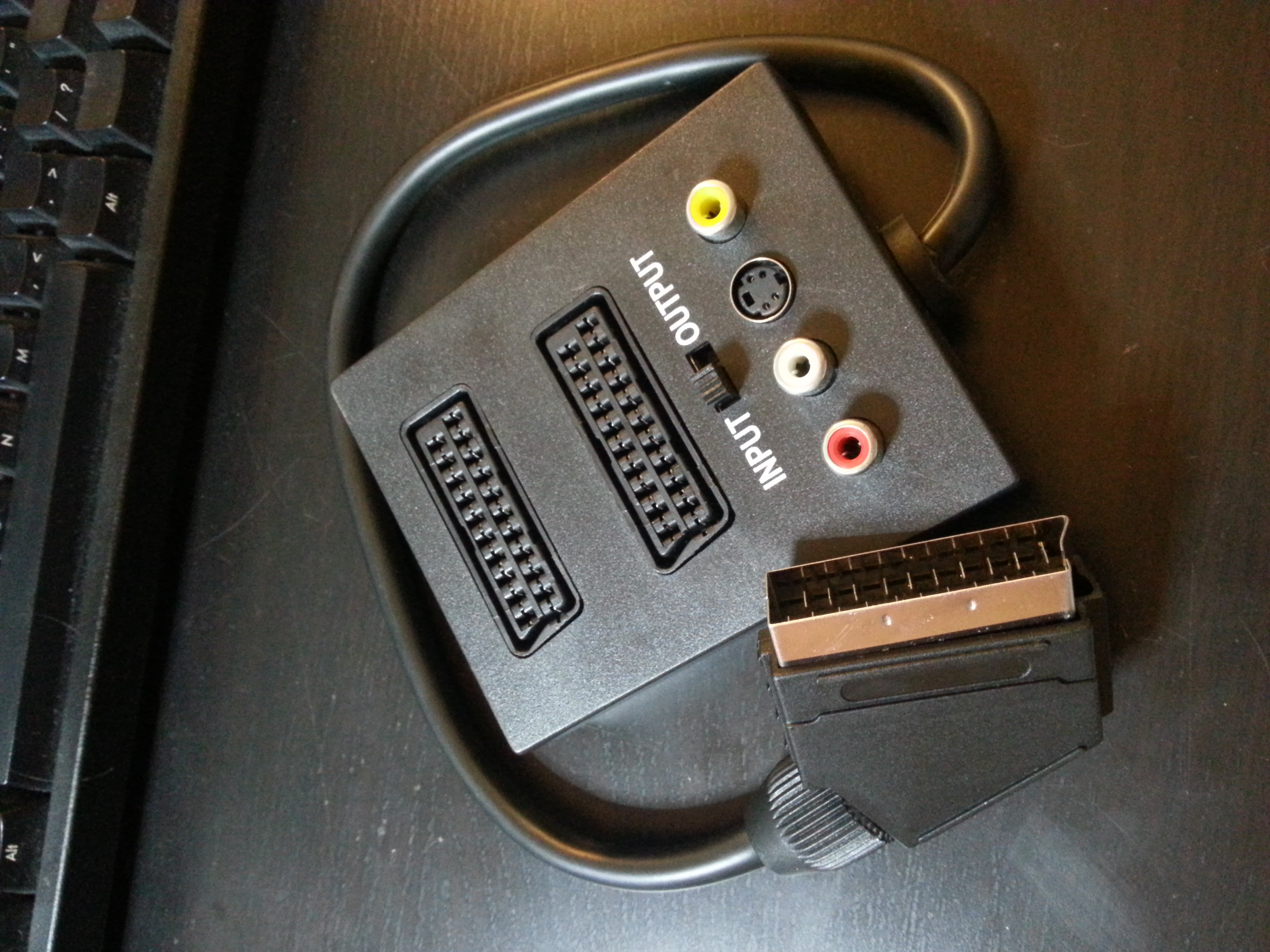
- Bought a super cheap crappy dual female to single male SCART thing.
19/01/17
- All components arrived.
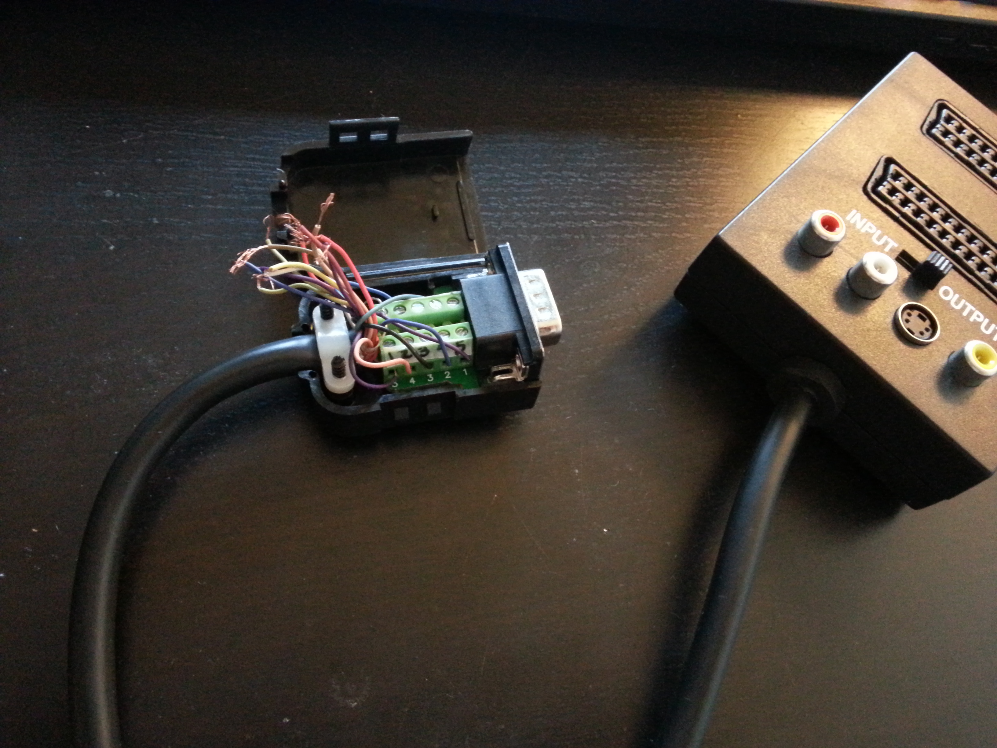
- Started to combine the SCART thing with the DB9 connector (BTW: next time need to buy a simple one to solder on, this one is overkill)
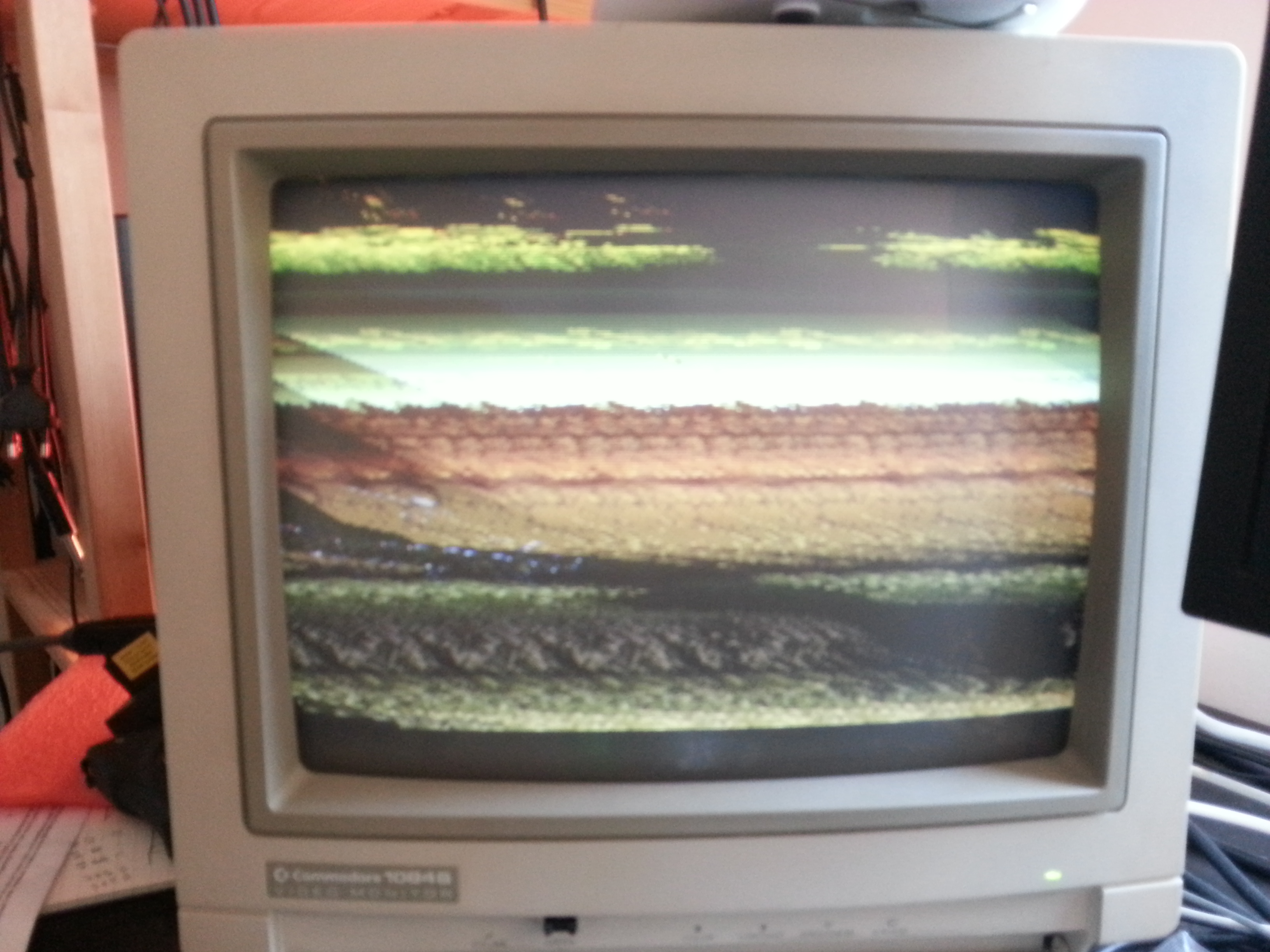
- The image is out of sync, problem with composite sync signal not being picked up properly. Need to investigate (contrast, color, sharpness really good though, did not expect this quality).
21/01/17
After reading from several sources, it seems that not all 1084S are built the same, it also appears that even specific models (this one here is a 1084S-P1) have been built differently. Bottom line some models will pick up sync from the composite signal, some won't. There seems to be two options for me: mod the monitor or build a simple sync stripper to extract the sync signal (called csync) from the composite signal. I think I will go for the second option, modding the monitor introduces changes in the way the composite signal needs to be fed and its effectiveness also relies on how the RGB DB9 pins are wired on the 1084S, as it seems, once again, is not done the same on all models
- TODO: find a LM1881 Video Sync Separator.
- TODO: check where I can get 5V from.
22/01/17
Today has brought a big AAAH AH! moment.
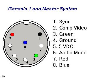
First I found a good article on composite sync. It confirmed what I had thought, that the console that I was trying to connect (Japanese Mega Drive model I) already generates its own csync. Here is a diagram from Game SX:
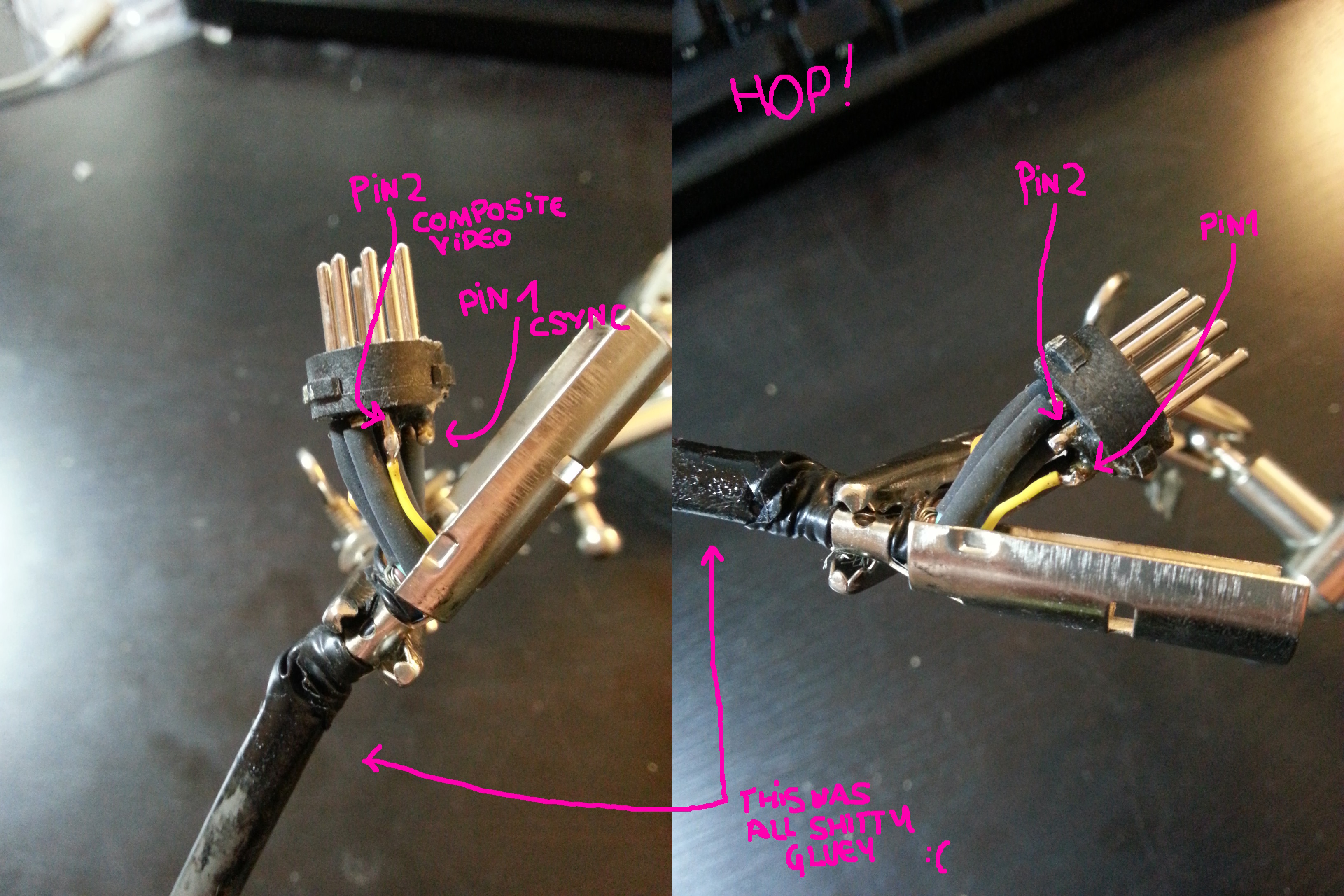
Because most CRT screens are happy using sync over composite instead of csync, it makes sense to take the habit to use composite as source of sync signal. I tested the pins of the Mega Drive SCART cable, and indeed the Pin 20 of the SCART (remember that's the one used for sync) was fed with pin 2 from the Mega Drive, and not pin 1, which was simply not connected.
A little bit of resoldering...
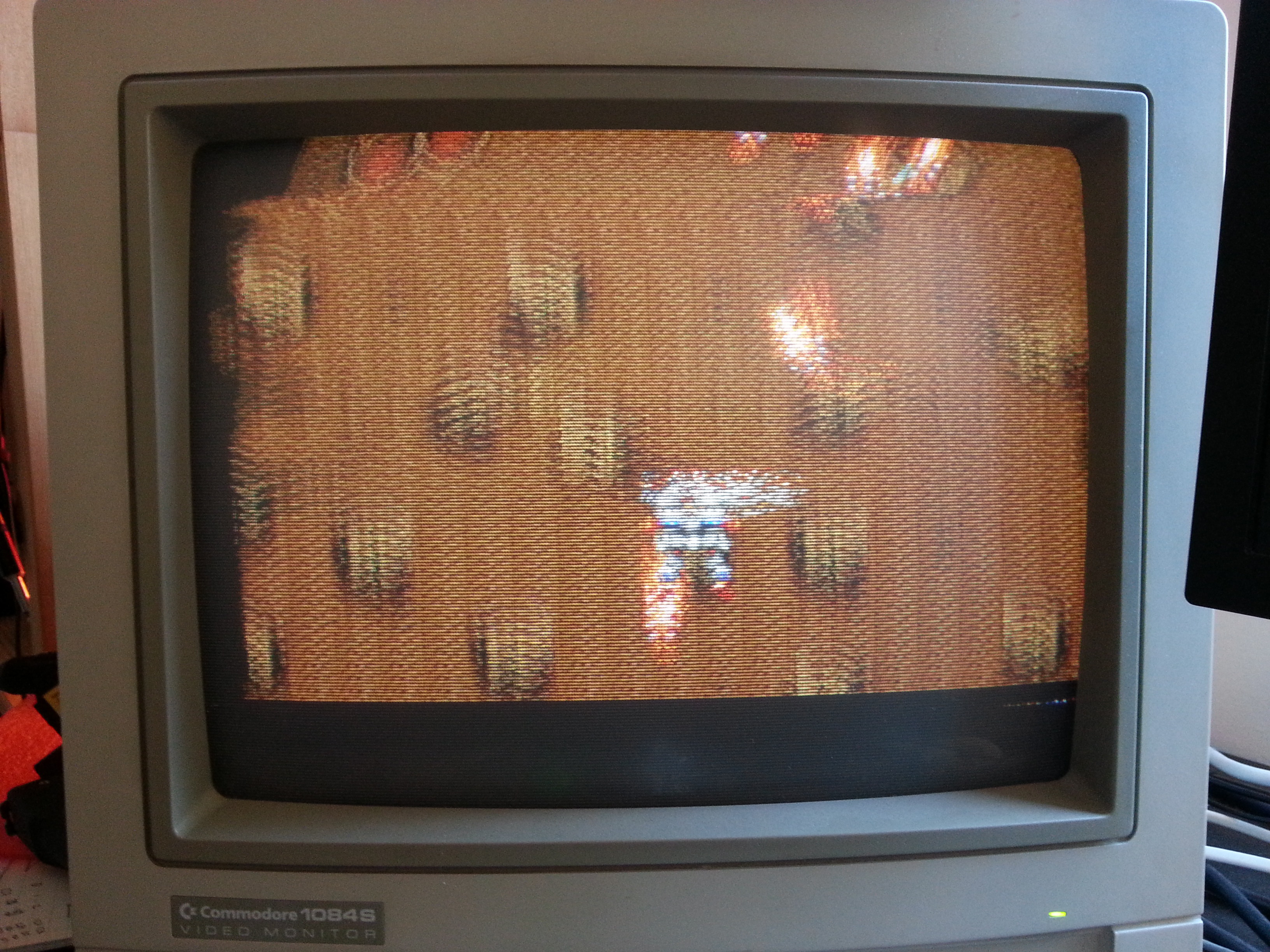
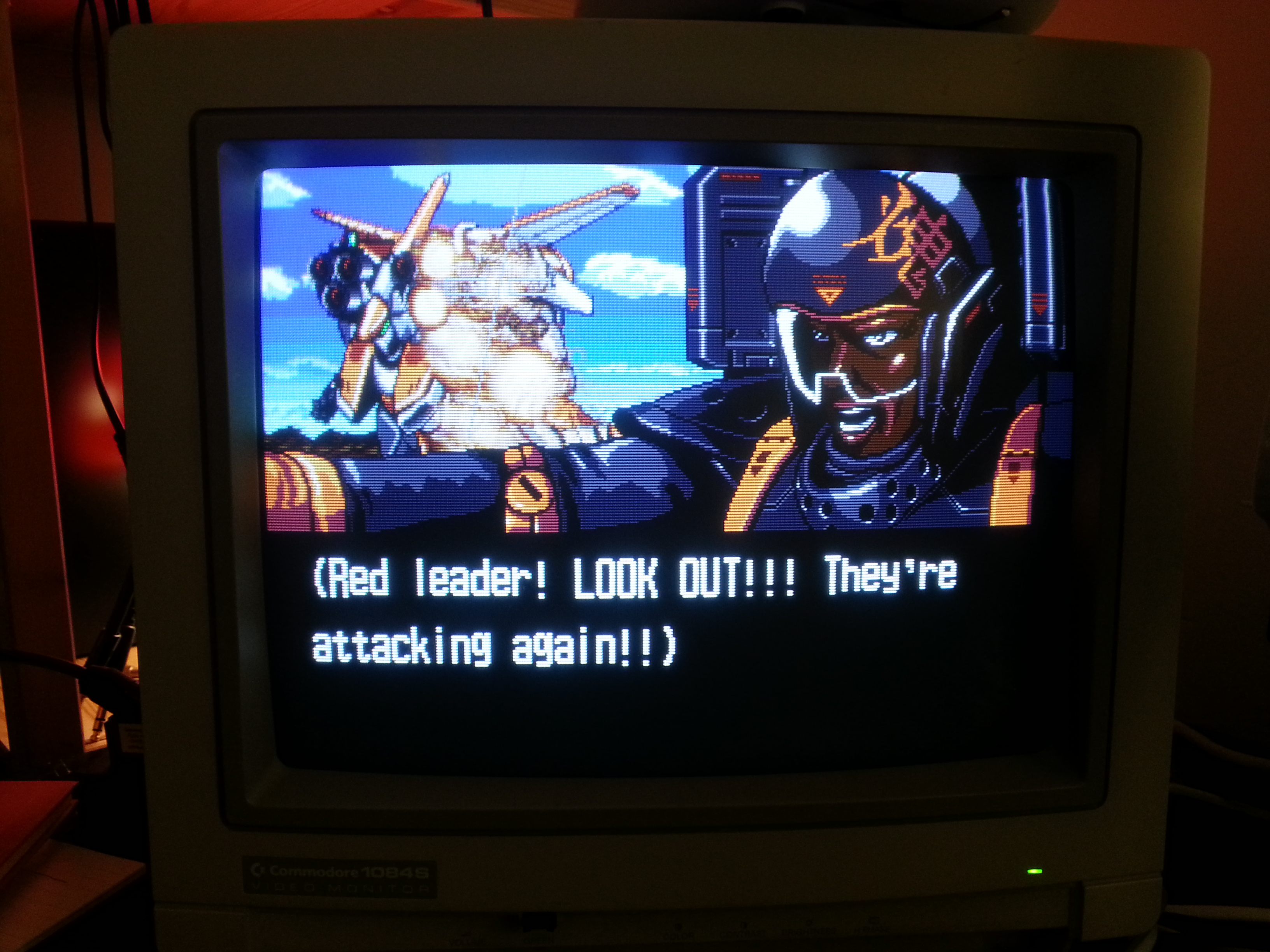
...aaaaaaand!
In the process I also noticed that my 1084S-P1 DB9 plug pinout was slightly different from the schematics I found, it was more like that:
   The 9 pins on the 1084S-P1 connection are:

               5 4 3 2 1
               | | | | |
              ___________
             ( o o o o o )
              \ o o o o /
               ---------
                | | | |
                9 8 7 6

   Pin 1 .......... Ground red
   Pin 2 .......... Ground green
   Pin 3 .......... Red video in
   Pin 4 .......... Green video in
   Pin 5 .......... Blue video in
   Pin 6 .......... Ground blue
   Pin 7 .......... Horizontal sync (TBC)
   Pin 8 .......... Vertical Sync (TBC)
   Pin 9 .......... Composite sync in
So what about the sync stripper circuit? Well I'll postpone that to when I'll have to plug something that does not provide its own csync...
