Maintenance PVM-2130QM
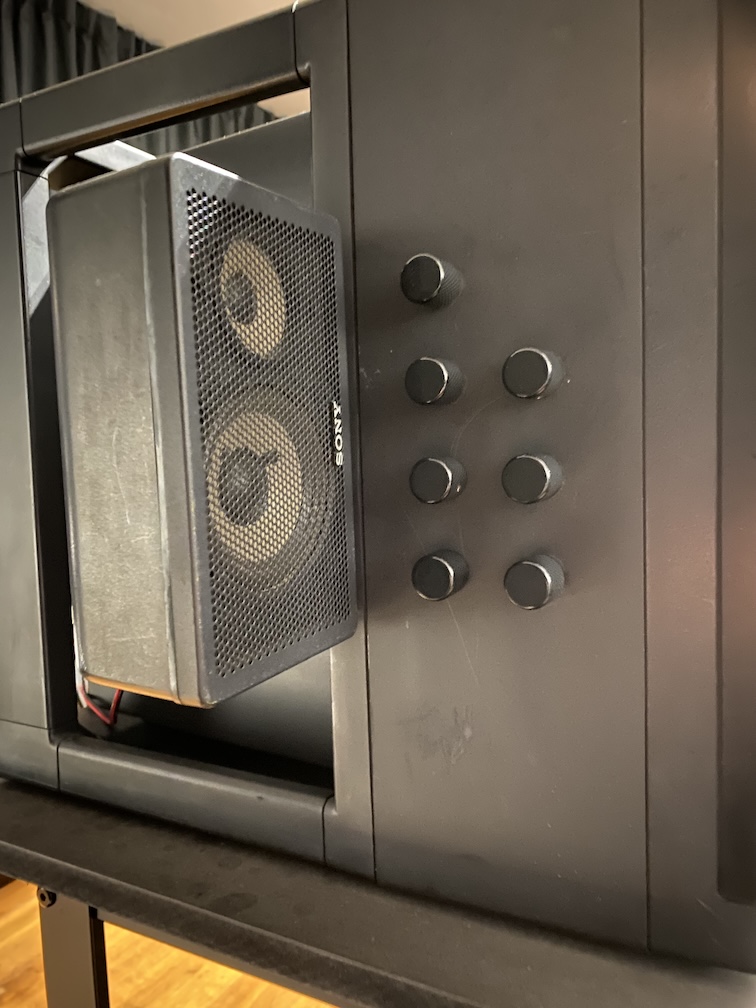
Some notes taken while trying to do some maintenance on this fine 1986 CRT monitor :)
The Sony ProFeel Pro (1986) monitor, commonly known as the Sony Cube, represents a high point in the developmental history of monitor technology and product design. This monitor incorporated the bright high-quality Trinitron screen (the brand name for a product line of aperture grill-based CRT screens) that had been developed during the 1960s, and which then underwent successive improvements. The definitive cuboid form of the Sony ProFeel Pro (1986) had not previously been a feature of monitor casing design in Sony’s range. Formerly, the dimensions of the back edge of the monitor had not been identical to the front; instead, the casing at the rear of the screen had been visibly narrower. In contrast, and distinctively, however, the Sony ProFeel Pro articulates the quintessential cuboid form, with its operational components removed from view and suspended within the back frame. The cuboid shape of the monitor casing facilitates the stacking of monitors, while also functioning as a grip-bar, which assists in carrying. These practical attributes of the design substantially enhance the utility and versatility of the equipment for exhibition purposes. (source: https://www.theblock.art/equipment/sony-cube-21/)
Opening the thing
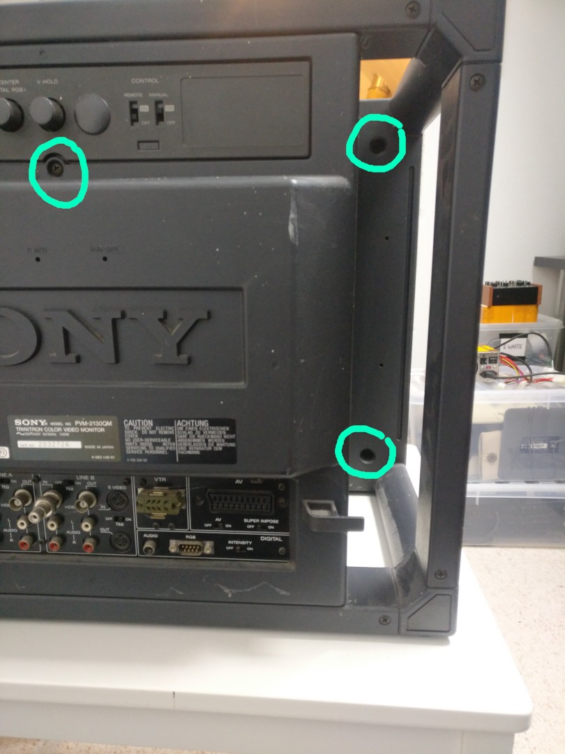
Looking at the back of the monitor or quickly browsing through the service manual exploded views gives an overwhelming feeling of stepping into the land of a million screws, but in fact, only 5 needs to be removed and it's pretty easy.
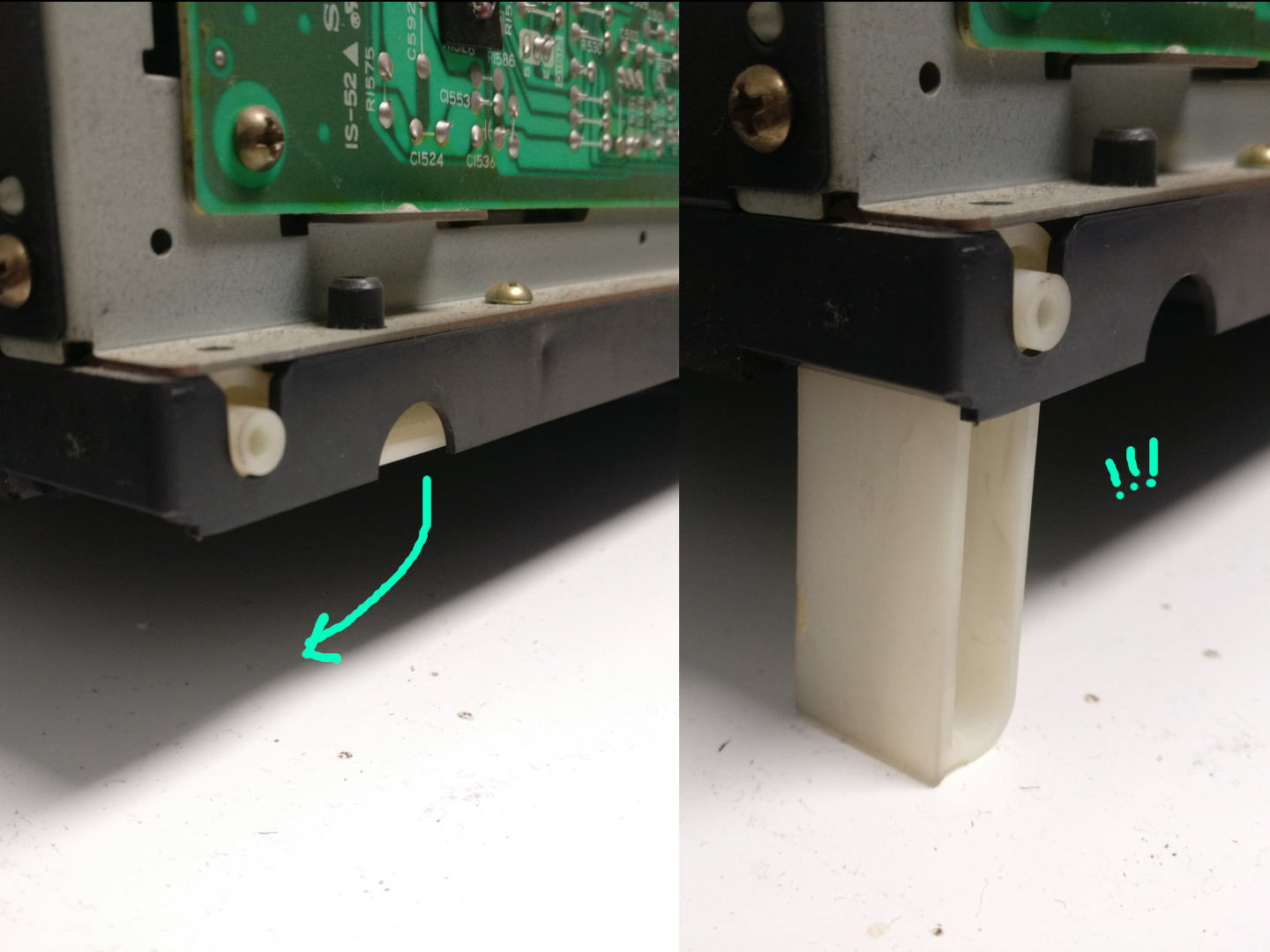
You can open by sliding the rear back (it can be a bit stuck, fear not, no surprise hooks or locks, just pull/shake gently). Once done, you will loose some balance and put pressure on the inner block that is now without support, but there is small undocumented cute detail: to maintain stability, the inside PVM rear inner block comes with mini legs :3
Messing around with the thing
General Convergence
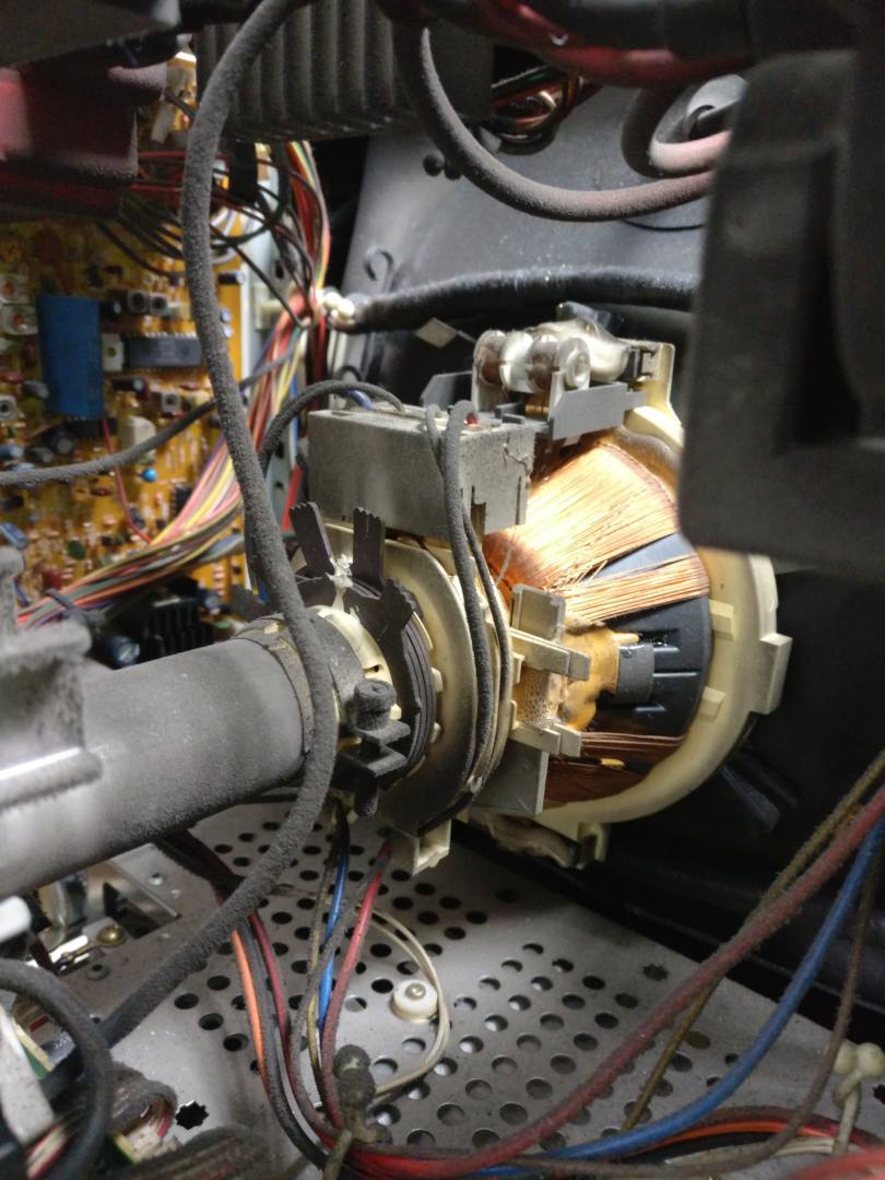
If I understand correctly part of the convergence maintenance is done by tweaking the magnet rings around the yoke. The bad news is that 1. they seem to be sealed for stability and 2. the yoke is a bit hard to reach in this monitor, and it's a part that's likely to lead to electrical shock while manipulated live. However, there is a good news, the monitor documented in this section did not have significant convergence issue, so I will procrastinate a bit this part of the maintenance.
Corner convergence
Convergence is generally done through yoke manipulation, however, in the corner of the CRT things usually start to degrade and the usual way to correct it is by having small magnets taped on the tube in a position that fixes such degradation. With age this tape may be loose, or the magnet fell, etc. In which case or or several corners may start to look distorted with chromatic aberrations.
TODO: check the magnets of the corner afflicted by this
Tilt
Same remarks as previous section. Tilting is basically done by rotating the yoke manually. In theory it needs to be made slightly loose (see the screws in photo above) and rotated. Because of high voltage I need to read more before tempting to put my hand in there.
Geometry
Geometry can be adjusted on the PCB marked as "D", it's the biggest one, on the right side of the inner block, if you look from the back. The following settings can be adjusted (probably more, but these are the most likely to be useful).
- RV554 Horizontal Size
- RV555 Horizontal Center
- RV553 Pin Phase (aka skew)
- RV552 Pin Amp (aka pincushion)
- RV503 Vertical Size
- RV509 Vertical Center
Caution: the post are mounted on the other side of the PCB, access to the rear of the pots is possible with see-through-holes. You'll need a tiny insulated screwdriver and be careful, does not look like these pots are super solid.
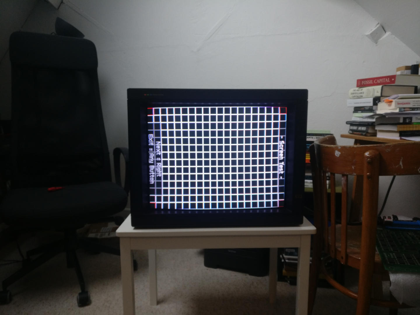
To adjust geometry you need a test signal with some geometric patterns obviously:
- Arcade PCB: usually they come with a service menu that has some patterns specifically for the board
- Consoles: use the 240p Test Suite
Focus
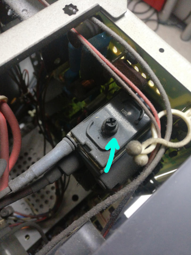
The focus can be adjusted by tuning a screw on the side of the flyback transformer. The screw controls the focus voltage sent to the electron gun.
Caution: Did not check the spec of this one, but the flyback is basically generating high voltage DC, and the focus voltage is probably in the 6-7KV range. Unless you mess around or touch visible capacitors (did not see any from the side that matters to us), it's fine.
Manual degauss
If your monitor has spent too much time near a magnetic source (unshielded speakers for instance) or when you rotate the screen (for instance going from YOKO to TATE) you may notice that some parts of the screens have strange color hue issues. This is due to remnant magnetic field in the CRT. This generation of PVM in particular seems to be particularly sensitive to earth magnetic field when rotated. It's possible to temporary or permanently fixed the problem (until the next time the monitor is moved around) by reducing or removing such remnant magnetic field. This process is called degaussing. 90s CRT tend to be equipped with a degauss coil that's started automatically when the monitor is turned on, sadly this monitor does not have such a thing, and therefore it needs to be manually degaussed.
TODO:
- magnet?
- DIY degauss coil?
Potential mods
Obvious mod would be to redirect the geometry pots to a small outside board, because that's the kind of stuff that needs to be adjusted from one Arcade PCB (or console) to another, and opening the CRT every time for that is totally absurd.
A list with the pot values follows (values in parenthesis are the measured values):
- RV503 V. SIZE: 220 Ohm (216 Ohm)
- RV504 PIC-BOW: 22 kOhm (19.8 kOhm)
- RV509 V. CENT: 1 kOhm (1.033 kOhm)
- RV552 PIN AMP: 22 kOhm (19.5 kOhm)
- RV553 PIN PHASE: 1 kOhm (1.105 kOhm)
- RV554 H. SIZE: 47 kOhm (43.5 kOhm)
- RV555 H. CENT: 3.3 kOhm (2.97 kOhm)
For completeness, this is the value for the extra pot that adjusts the horizontal frequency:
- RV501 H. FRE: 4.7 kOhm (4.42 kOhm)
NOTE 1: All potentiometers should be linear with 20% tolerance.
NOTE 2: RV509 (V. CENT) is another type of trim pot on the PVM’s PCB (it’s also blue instead of yellow).
NOTE 3: RV501 (H. FRE) should be excluded from the mod (horizontal frequency requires special adjustment).
NOTE 4: There’s a blind on the back between V HOLD and CONTROL - REMOTE that can be removed to route cables from inside the PVM to outside.
NOTE 5: As an alternative to the 3.3 kOhm RV555, a 2.5 kOhm pot with two resistors around 330 Ohm on each side could be used instead. It will limit the total range, but it should be enough for adjustments.
NOTE 6: Consider using connectors (such as JST) to make the outside board removable.
NOTE 7: The left side of the PVM can be used to place full-size potentiometers if cutting is no problem.
