DIY SUROM Cartridge
The SUROM offers a rather comfy setup for developing large software for the NES and Famicom consoles:
- 512K (4Mbit) PRG
- 8K CHR-RAM
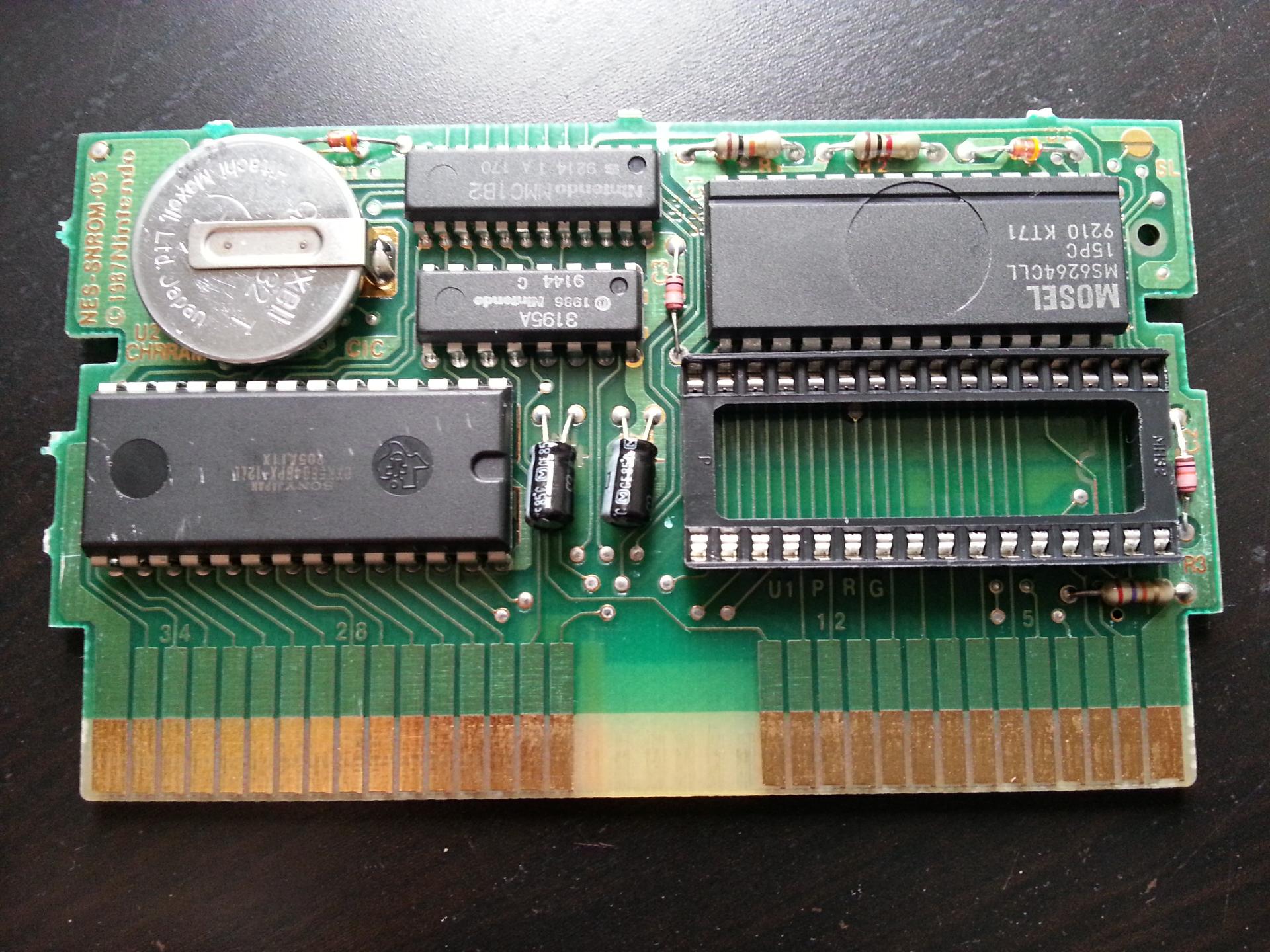
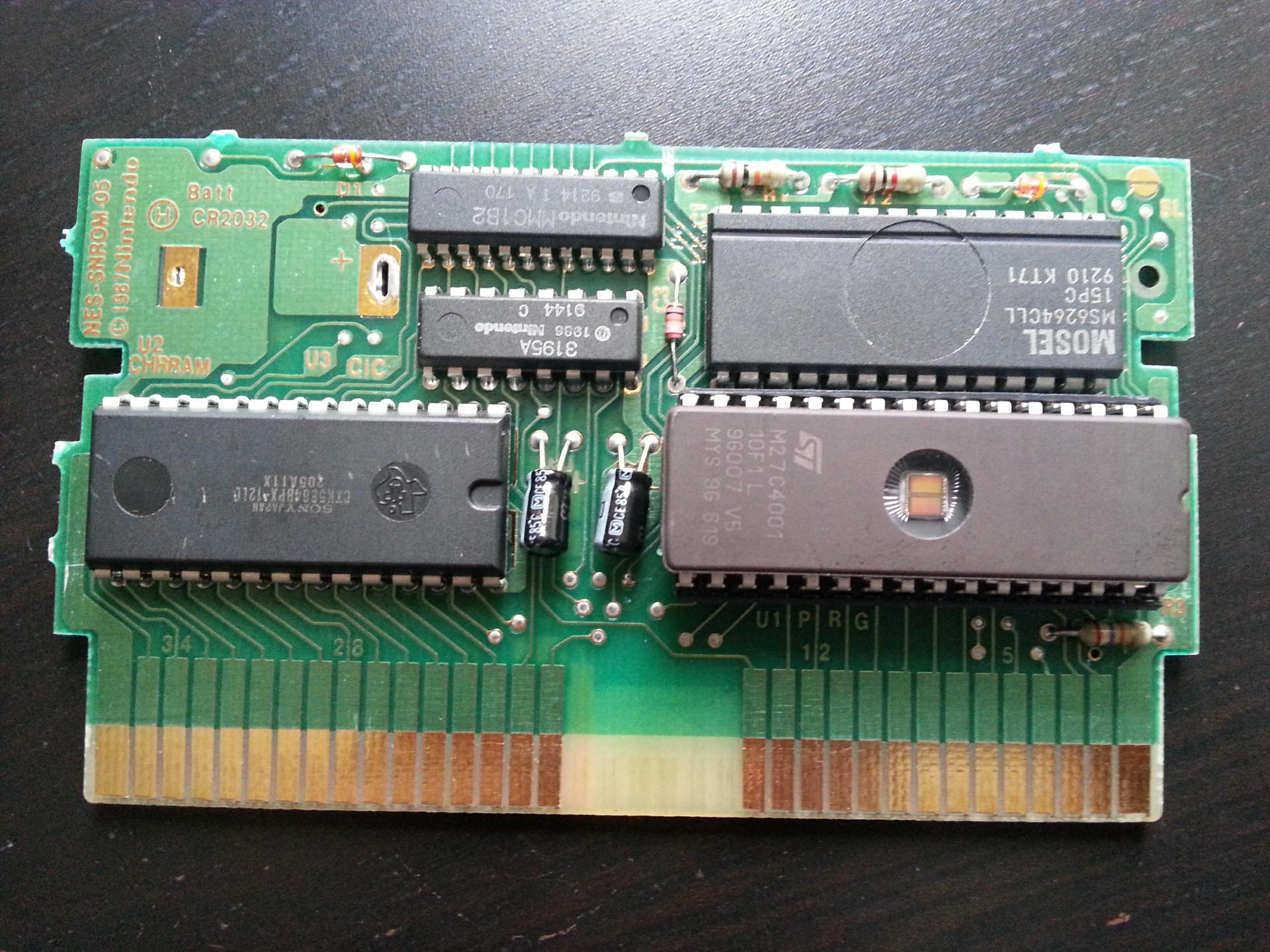
The whole operation simply consists of replacing the 512K PRG Mask ROM with a matching compatible EPROM (27C040, 27C4001) or EEPROM.
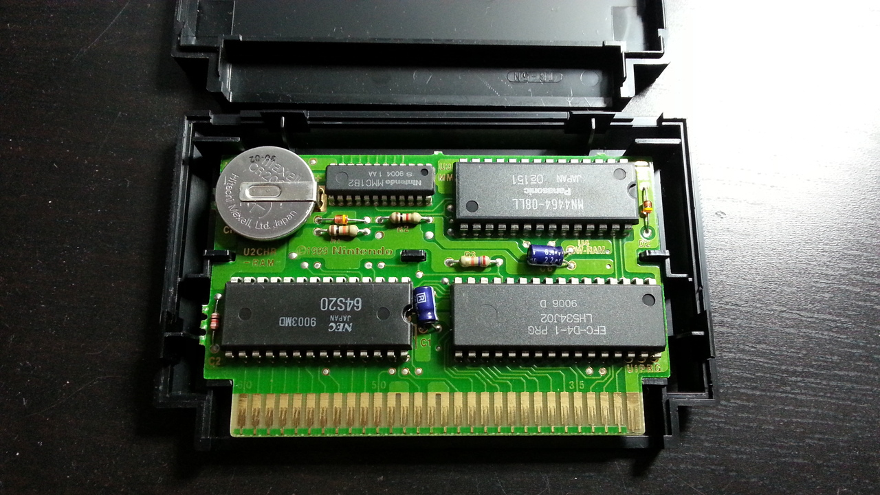
It's possible to use existing SUROM PCBs or convert other PCBs from the SxROM family to make a DIY SUROM Cartridge. At time of writing which strategy to use depends on the target platform:
- Famicom: there are several cheap over produced Famicom SUROM based games, so these can be used as donor carts.
- NES: all the NES SUROM PCBs are used by games that are collectible, with significantly higher than average price tags. It does not make much sense to use these. Instead it is easier to mod cheaper and less sought after games with a compatible SxROM PCB.
Understanding how things are wired on a SUROM
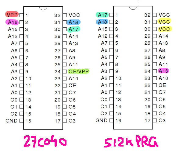
Taking an EPROM as example, here is the difference between a rewritable 27C040 (or 27C4001) 512K EPROM and the original 512K PRG Mask ROM found in a SUROM based game, as you can see they are almost identical and the difference can be compensated by rewiring a few things:
Most of the rewiring is related to connections to the MMC1 mapper ASIC used in SxROM PCBs. So studying its pin layout is needed:
MMC1 Chip:    (24 pin shrink-DIP)
----------
Comes in several varieties: 'MMC1', 'MMC1A', and 'MMC1B2'

                                  .---\/---.
                    PRG A14 (r) - |01    24| - +5V
                    PRG A15 (r) - |02    23| - M2
                    PRG A16 (r) - |03    22| - PRG A13 (s)
                    PRG A17 (r) - |04    21| - PRG A14 (n)
                    PRG /CE (r) - |05    20| - PRG /CE (n)
                    WRAM CE (w) - |06    19| - PRG D7 (s)
                    CHR A12 (r) - |07    18| - PRG D0 (s)
                    CHR A13 (r) - |08    17| - PRG R/W
                    CHR A14 (r) - |09    16| - CIRAM A10 (n)
                    CHR A15 (r) - |10    15| - CHR A12 (n)
    CHR A16 (r) or WRAM /CE (w) - |11    14| - CHR A11 (s)
                            GND - |12    13| - CHR A10 (s)
                                  `--------'

                                     MMC1

diagram source: http://nesdev.com/rom.txt
The rerouting of the traces is relatively straight forward if you cut or prevent access to the right traces and connect the pins of the EPROM (or its socket) to the right destination. However, there is a caveat. Connecting the pins means more maintenance work if the EPROM needs to be removed. This is not an issue if using a socket but only if you are soldering the EPROM directly. The alternative would be to modify the PCB so that you do not have to solder anything on the EPROM's pins. This is however more effort and require different tricks depending on the revision/model of the SUROM PCB. In this doc we will just solder the pins.
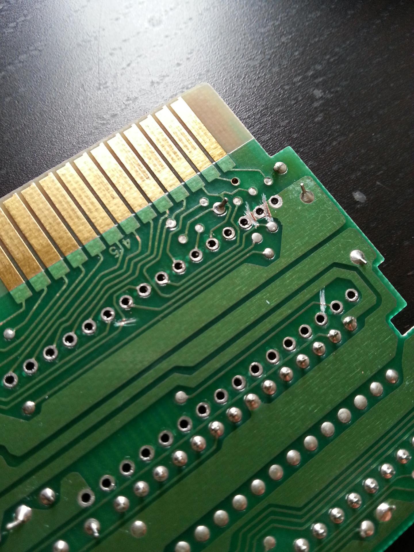
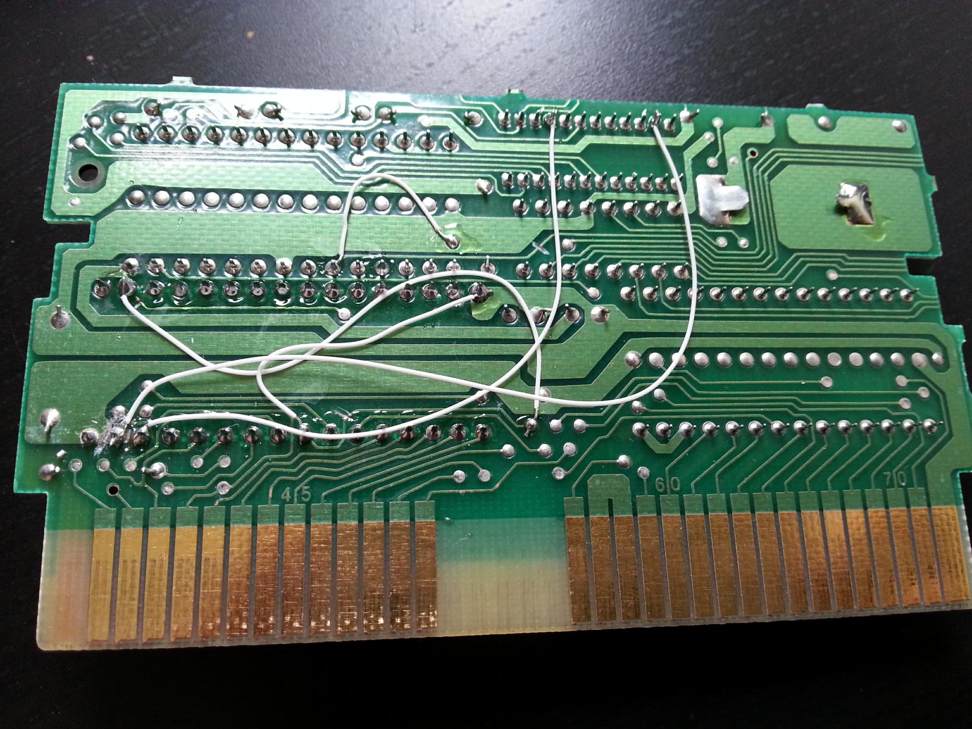
To do it, it's possible to either cut traces and wire the back of the PCB, or instead tape the PCB holes we do not need and lift the matching socket/EPROM's pins and then wire the front of the PCB. None of the two are ideals, they both have pros/cons. Taping is faster and we will use that for the Famicom doc, but for the NES doc we will use the trace cutting option because the front PCB is too packed to solder extra wires.
Famicom SUROM PCB
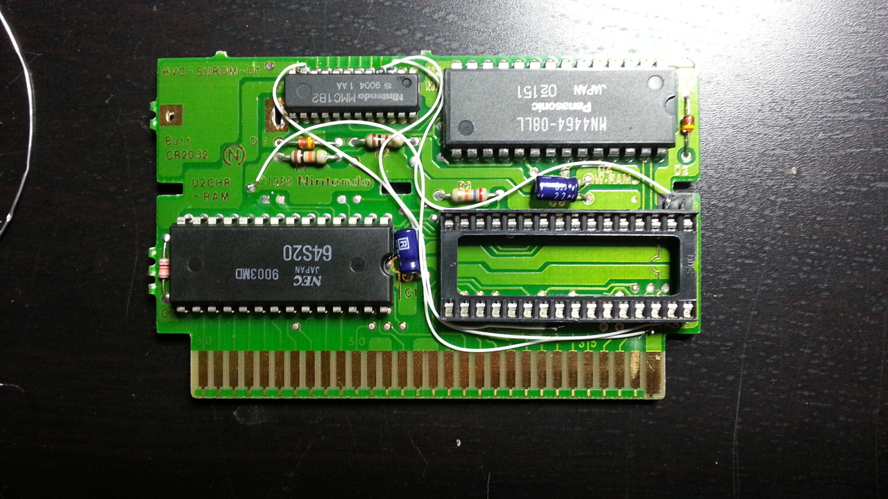
- Find a cheap Famicom SUROM based game
- Open the cartridge
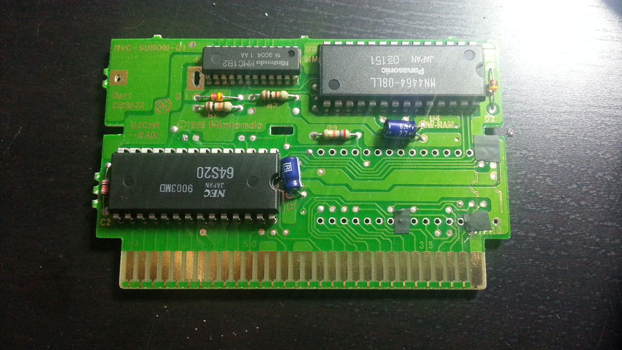
- Desolder the PRG Mask ROM, and optionally the battery if you have no use for it.
- Mask holes 1, 2, 24, 30 and 31 with electrical tape.
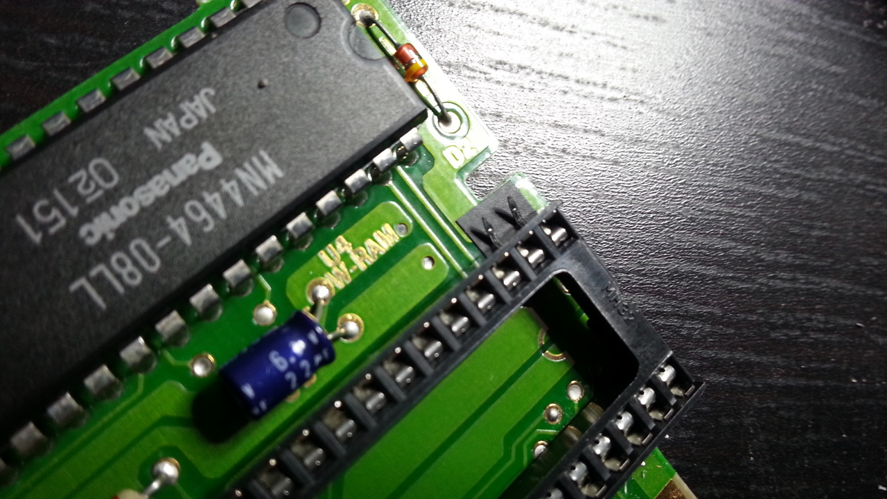
- Lift pins 1, 2, 24, 30 and 31 of the socket or the EPROM and solder it.
- Solder wires between:
- socket/EPROM pin 2 and MMC1 pin 3
- socket/EPROM pin 31 and MMC1 pin 11
- socket/EPROM pin 30 and MMC1 pin 4
- socket/EPROM pin 24 and GND (any will do, I use the one near the copyright mark in the photo below)
- DONE! If you solder the EPROM directly you can close back the cartridge, otherwise if you need a shell, you will have to make a hole in the plastic to allow access to the EPROM as it won't fit all inside. Anyway the whole point of using a socket is to remove/test different EPROMs so access is kind of obviously needed...
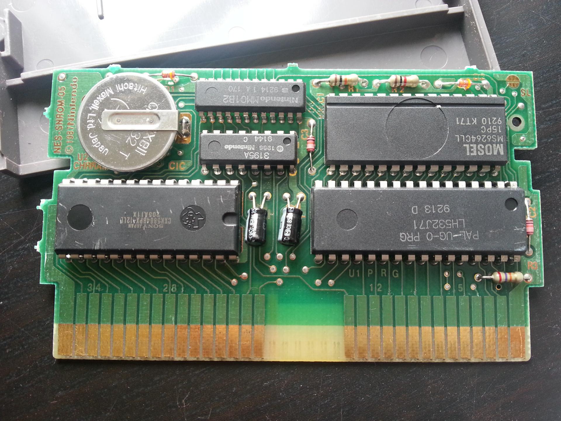
NES SUROM PCB (with an SNROM base)
Then main difference between using a SUROM directly and modding an SNROM is minor. The MMC1 mapper pin 11 does not need to be configured to connect to the WRAM but instead connect to the PRG ROM. The rest is the same.
- Find a cheap NES SNROM game
- Open the cartridge
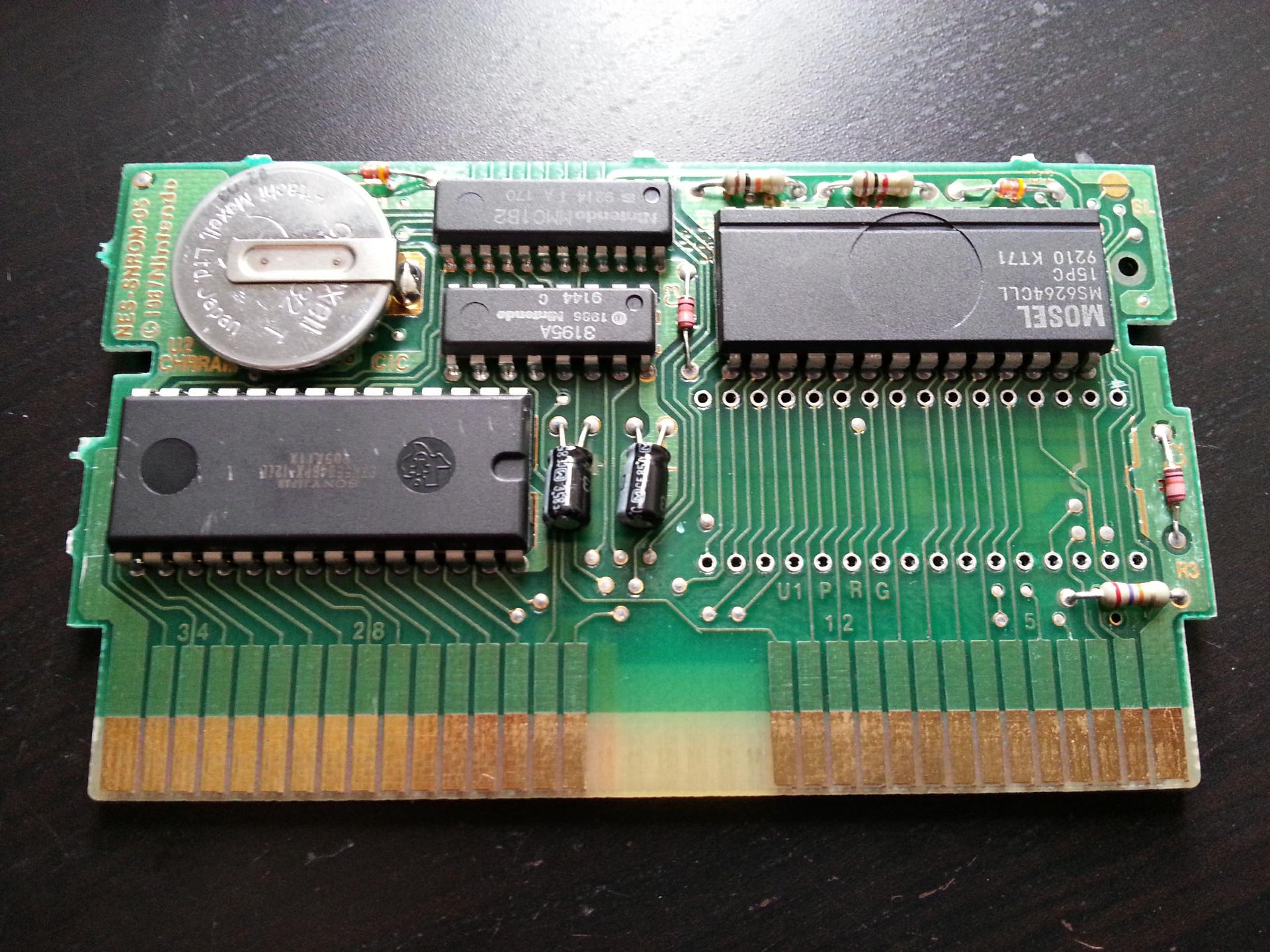
- Desolder the PRG Mask ROM
- Cut the PRG tracks 1, 2, 24, 30 and 31
- Cut track from MMC1 pin 11 to WRAM pin 20
- 'Solder the EPROM socket OR solder the flashed EPROM directly
- Solder wires between:
- Socket/EPROM pin 2 and old source of PRG pin 24 (A16)
- Socket/EPROM pin 24 and PRG pin 16 (GND/OE)
- Socket/EPROM pin 30 and old source of PRG pin 1 (A17 / MMC1 pin 4)
- Socket/EPROM pin 31 and pin 11 of MMC1 chip (A18)
- WRAM pin 20 and GND
- Desolder battery holder if you don't need it.
- DONE! If you solder the EPROM directly you can close back the cartridge, otherwise if you need a shell, you will have to make a hole in the plastic to allow access to the EPROM as it won't fit all inside. Anyway the whole point of using a socket is to remove/test different EPROMs so access is kind of obviously needed...
- Optional: If you need your DIY NES SUROM cartridge to run on different NES consoles from different regions, or simply from a region different from the one the original game was meant to run, then check the Multi-Region NES CIC Clone page.
NES SUROM PCB (with an SGROM base)
- Cut track 1
