Backlit screen for the Game Boy
On this page we take a look at a popular mod: the backlit screen! The idea is to keep the original LCD of the GB in place, but we remove its reflective foil, and place behind it a small LED light diffusing panel. These panels can be found a bit everywhere and often comes in different (fixed) colors. They make the GB much more readable and will make you look cool and make your chiptune sounds at least 150% better. Usually this mod always come with another mod, the "bivert" mod, which improves the backlit mod by increasing the contrast a bit.
We break the procedure in two parts: first we mount the LED panel, and then we do the bivert mod.
Background history
Note: the following account is probably not 100% accurate. If someone reading this is more knowledgeable of the background history behind this mod, please let us know about it so we can improve this section!
The history of the backlight + bivert mod is a bit unclear, and hard to retrace given that the 8bc forum has disappeared with no known archives online. What may have happened was that once backlit modifications were introduced in the GB community, some modder(s) realised that by rotating the polarizing foil of the LCD backlight (needed because to install the backlight you must remove one), you would as expected get an inverted image, but with a higher contrast/sharpness. Eventually in 2009, some musicians wondered if some GB software like LSDJ could therefore have the palette inverted to benefit from the increased image quality, without the colour inversion. nitro2k01 documented a way to modify the LSDJ ROM to achieve such effect, but most importantly, two months later, they published a hardware mod that would provide the same effect using a small logic chip, essentially inverting the two data lines. Manual patching of ROM files were no longer needed. The biversion/bivert mod was born, and nowadays, the backlit mod and the bivert mod are hard to decouple.
LCD backlight
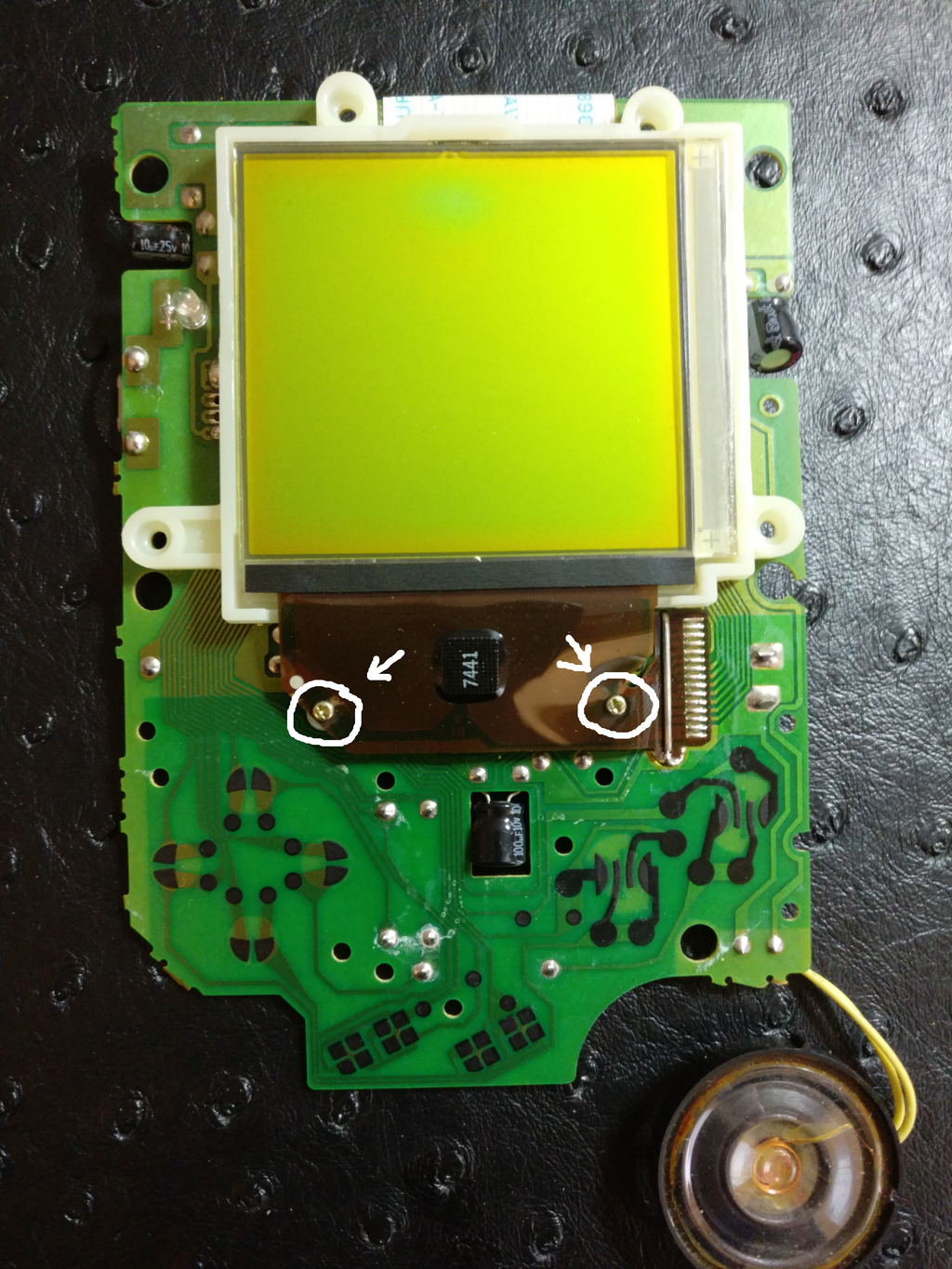
- First of all, let's remove the two very small screws that hold the front flexible PCB in place.
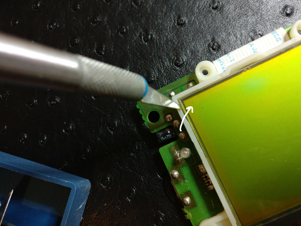
- Then with a utility knife, gently lift the LCD panel from the top left corner. There are some white sticky pad behind, so you may have to pull a bit.
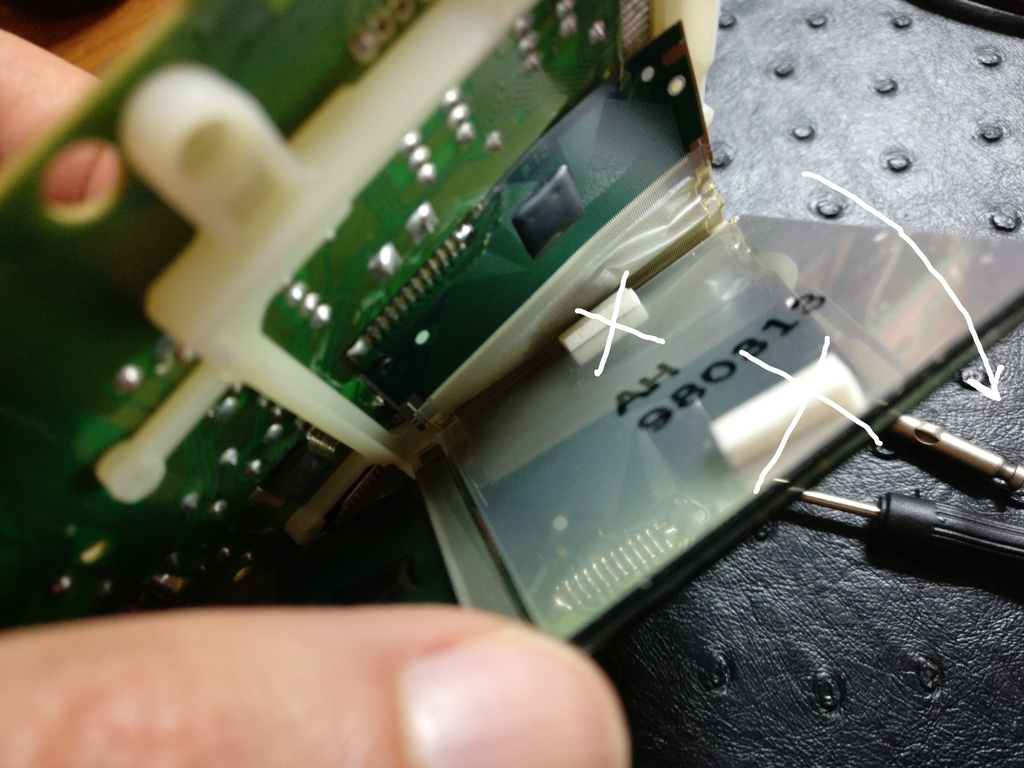
- You can't lift the panel fully because of the two flexible PCB soldered to the mainboard. You're going to get used to work in this strange position. Take a minute to remove the white pads, we won't need them anymore.
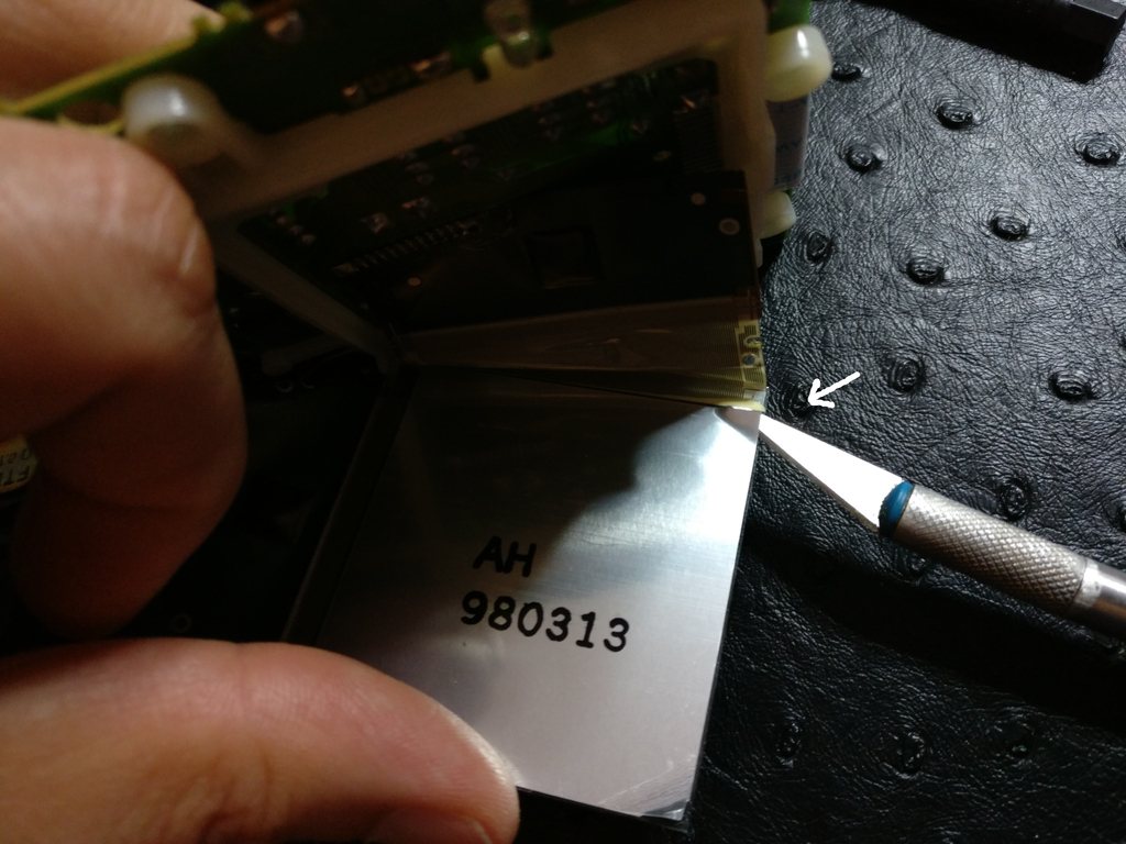
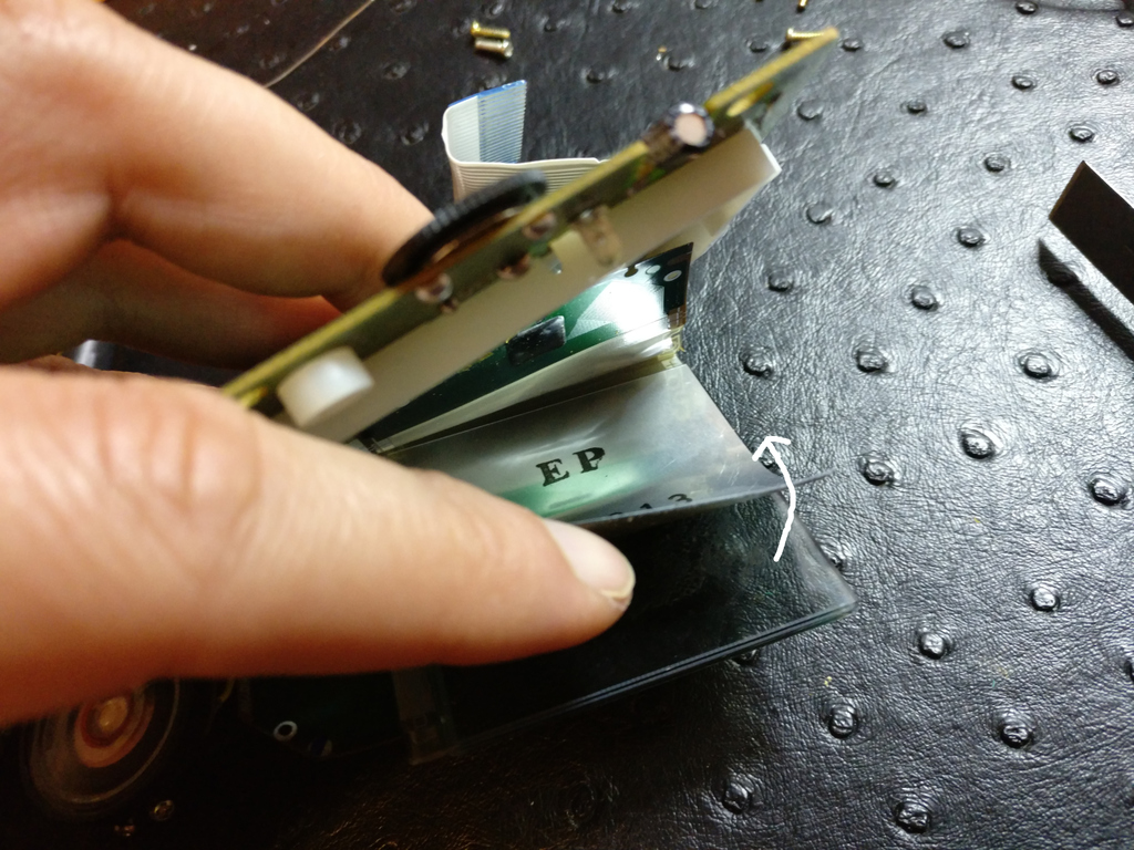
- With the utility knife, lift a corner of the LCD foil. It's tricky to get a sense of what you have to do the first time, the foil is made of three sheets: a plastic layer, a reflective layer, a polarizing film. Together it forms a quick thick and sturdy foil. The foil is glued to the LCD panel which is made of two glass layers. The knife blade needs to go between the foil and the LCD panel.
- Once lifted, gently and slowly peel the foil. It's going to take some time, don't rush it. Peel too fast: LCD breaks. Put too much pressure on your grib: LCD breaks. Pull too much surface at once: LCD breaks.
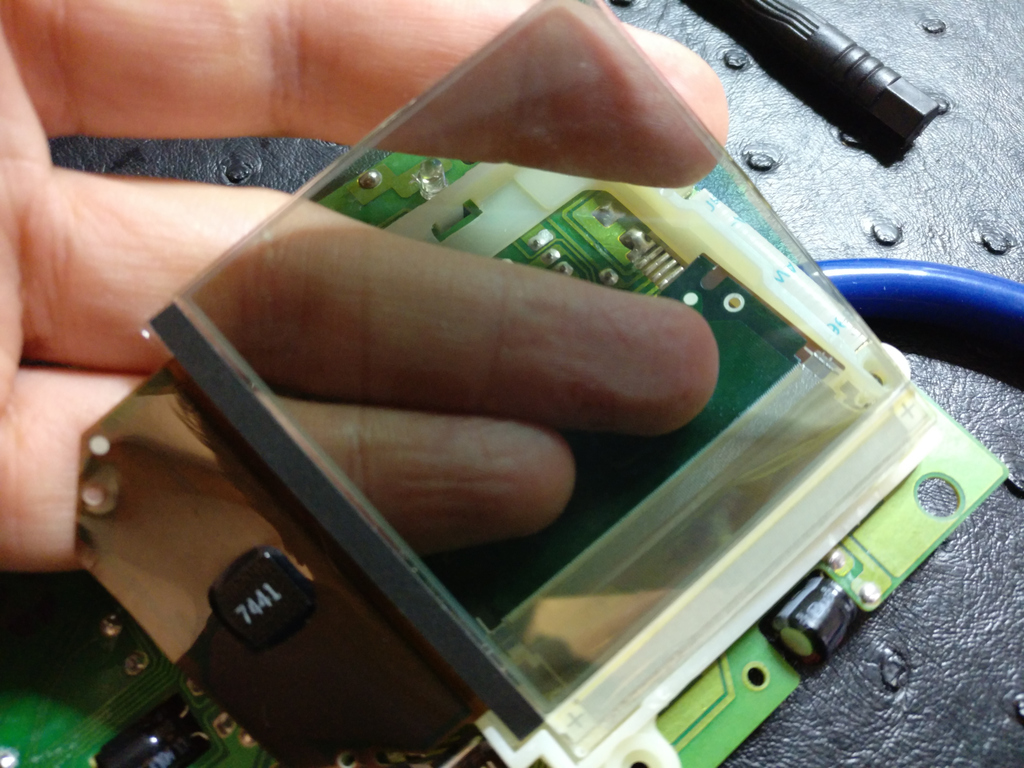
- Once done you're left with just the glass LCD panel. If needed clean it with isopropyl alcohol. Make it glue/dust free. Sometimes large amount of glue can remain on the glass, you may have to use something stronger like nasty sticker removal solvents.
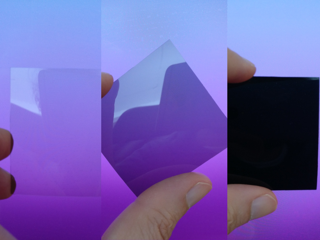
- Your LCD backlit kit should have come with a small polarizing filter (if it has protective plastic sheets, remove them), Use an LCD screen to find the right rotation, you need to have it rotated so that it passes the light fully.
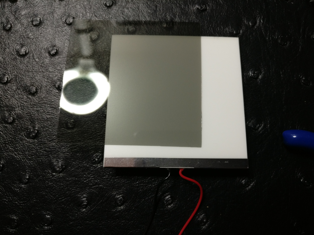
- Once in the right position place it on top of the LED panel (if it has protective plastic sheets, remove them).
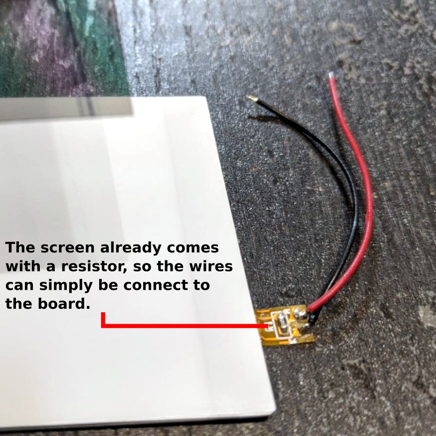
- NEW BACKLIGHT KIT: Looks like this one below, comes with a flexible PCB with an already soldered resistor.
- OLD BACKLIGHT KIT: If you're using an old backlit kit, then chance are that your LED panel does not have a flat connector, but wires directly attached to it. If that's the case, you need to cute the LCD panel frame so that the wires can go through. If your panel has a small flexible ribbon on its side (NEW BACKLIGHT KIT), then no need to cut, it will fit fine and the wires will be outside the frame.
- Slide in the panel with the filter on top.
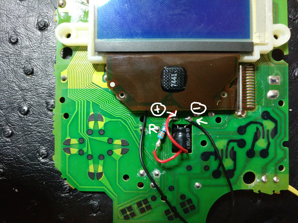
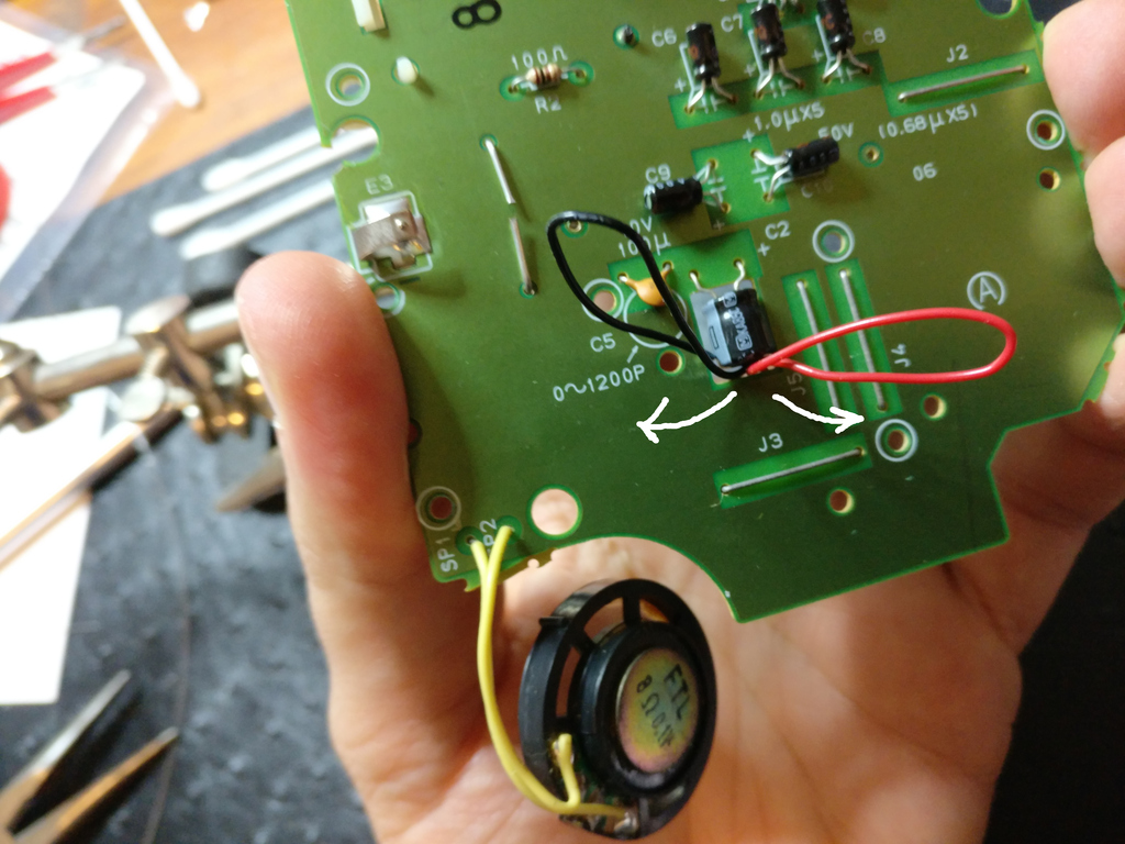
- OLD BACKLIGHT KIT: Solder a small 33Ω resistor to the + wire of the panel (red). Your kit may come with a different value, stick with what your kit is providing. Solder the resistor and the black wire as shown below:
- pull the excess wire through the capacitor hole so that it does not get in the way of the controller's contacts.
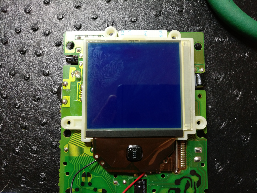
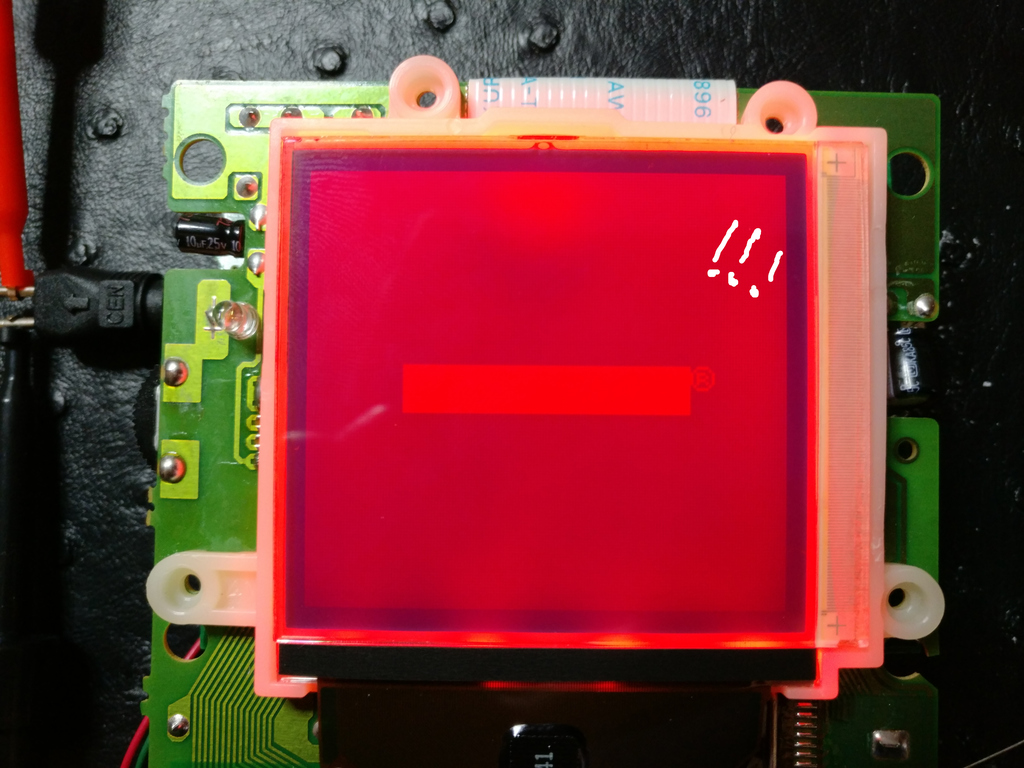
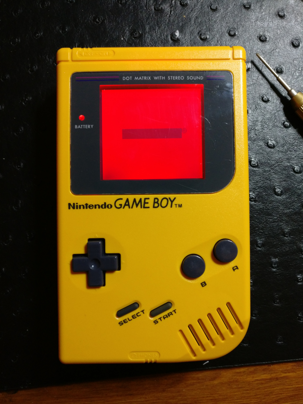
- Plug the LCD module back and test. You should see a inverted image. That's normal, once the bivert mod installed, it will look normal again.
Bivert mod
The bivert mod can be done in two ways: either using a ready made board that can be wired quickly to the GB, or by wiring the chip directly into the right places. We will show both ways.
Option 1: Bivert board
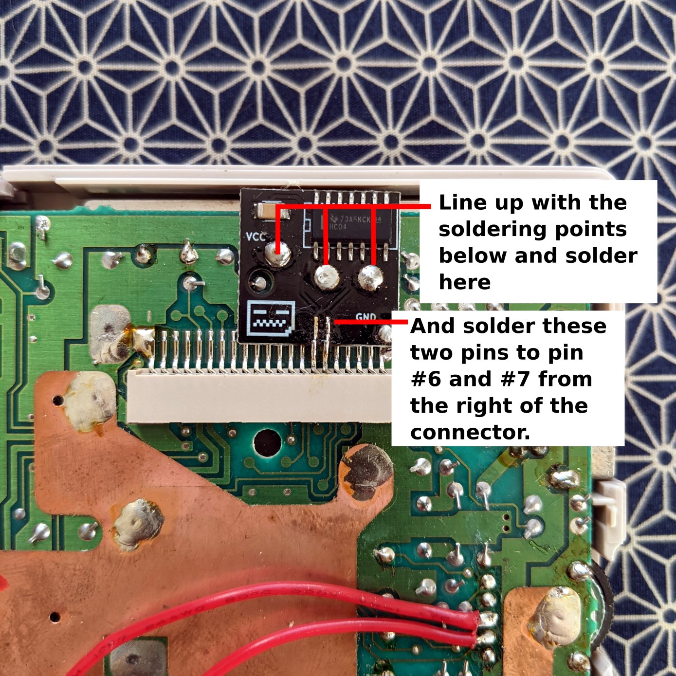
These can be purchased in various places, and comes in different shapes, but are doing all the exact same thing. In this section we're using a board made by deadpanrobot
Take care when lining up the bivert board, making sure you have enough room at the top for the case to close again nicely.
Also, when soldering the bivert board onto the screen connector, it is very important to take you time to desolder the existing connection, so that the pins themselves are clean. Please use desoldering pump or braid to achieve this.
Option 2: Bivert chip
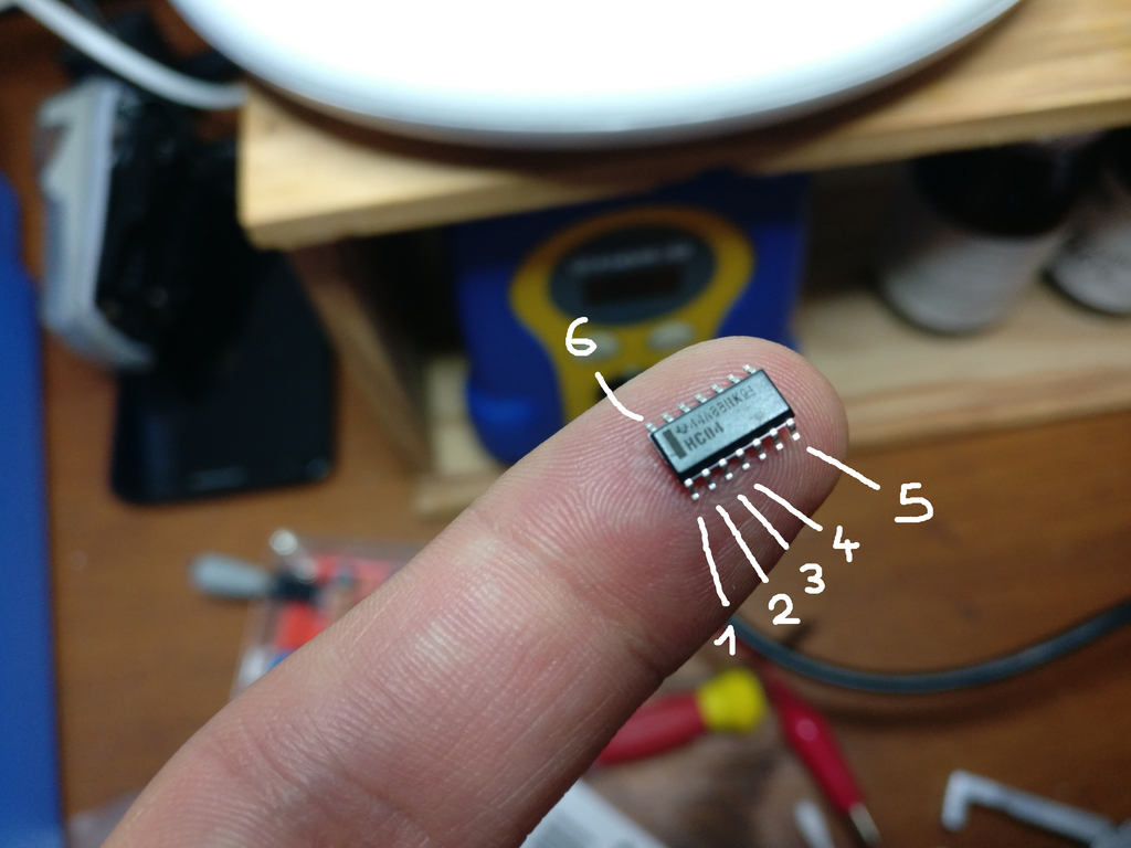
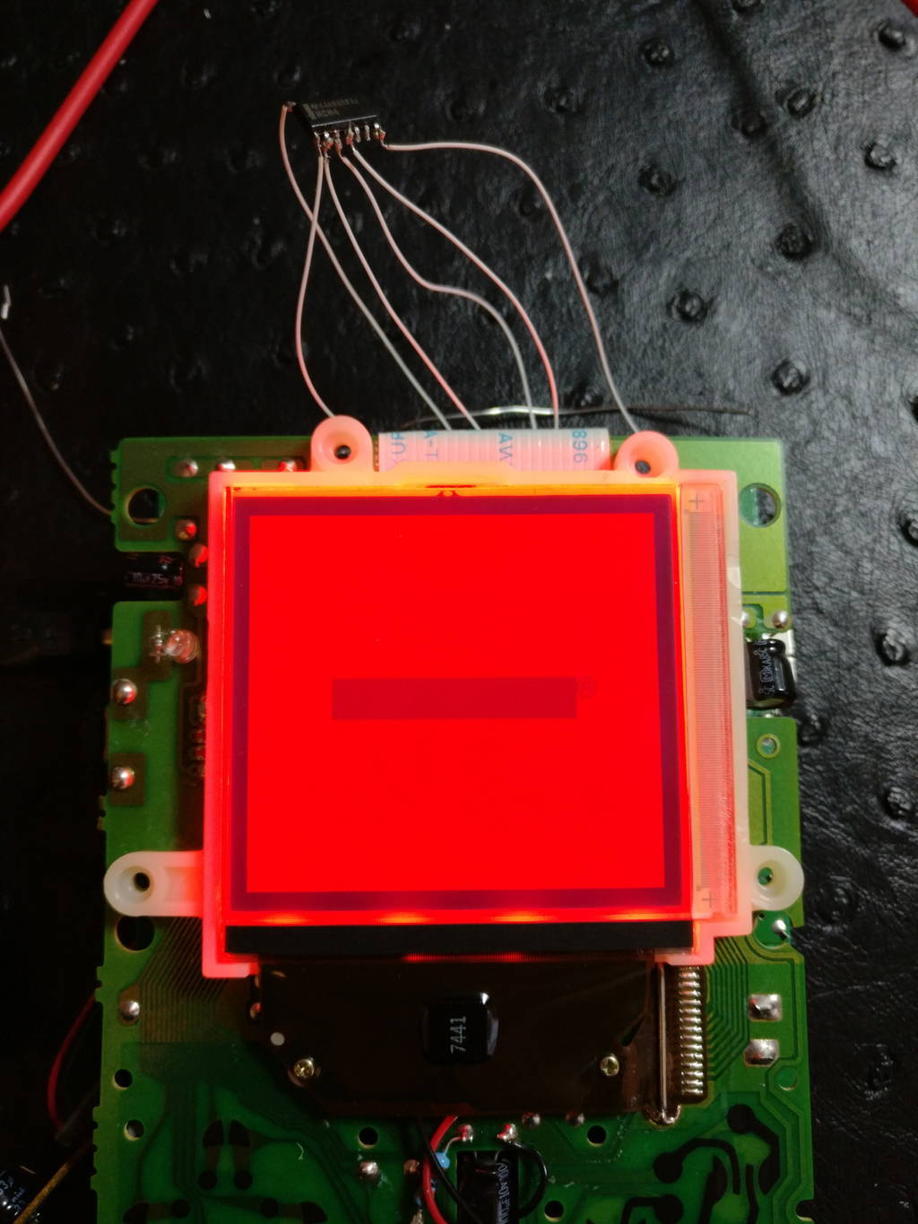
- A bivert chip is basically an hex inverter chip. This one below is a HC04 in SOIC-14 format. They can be found for very cheap. So if you're happy to trade convenience for fun and profit, you know what to do :)
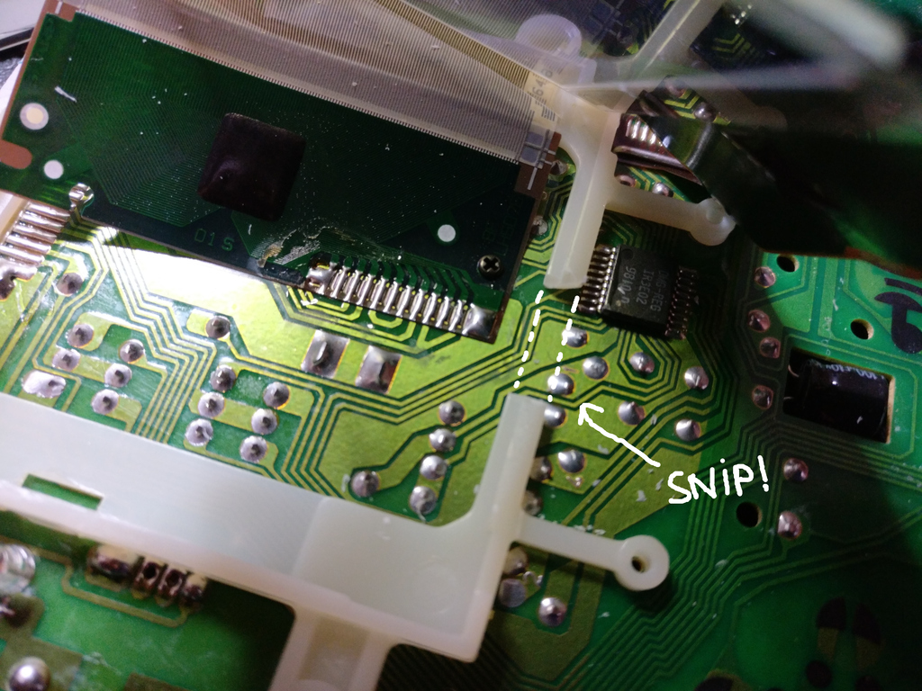
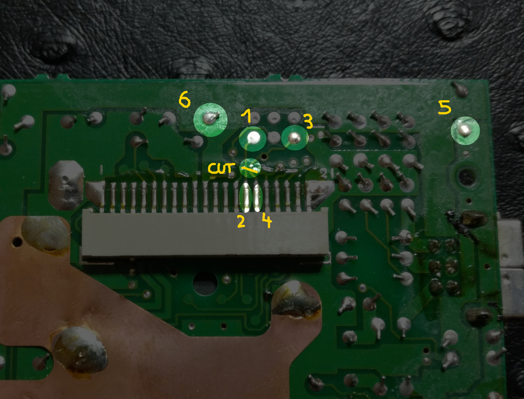
- First cut the PCB traces between 1 and 2, and between 2 and 4. Then wire the chip legs to the matching points on the PCB.
- Quick test, and you should now have a normal image!
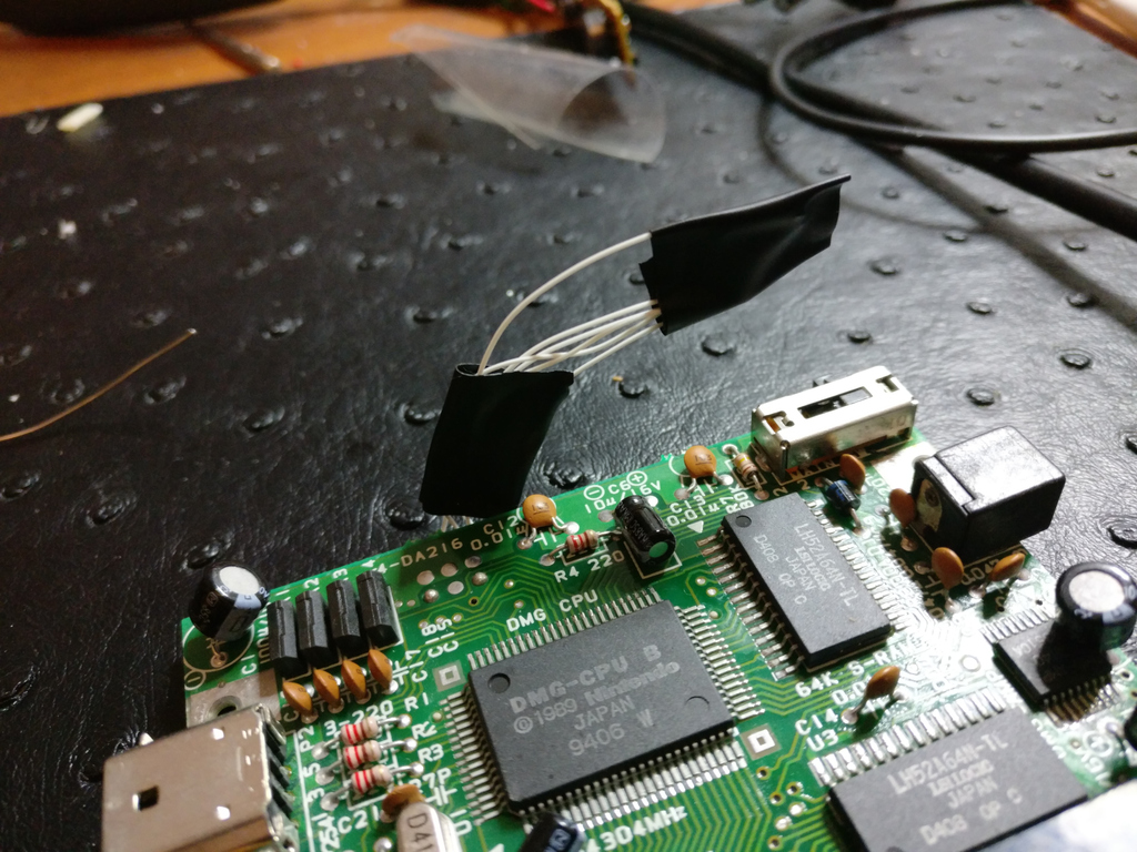
- Tidy up, because it's a bit fragile as it is. You can stuff it all on the other side, on top of the CPU, RAM, etc.
Putting it all back together
Now it's time to reassemble everything. A word of caution though: if you're using an OLD BACKLIGHT KIT that's a bit too thick to make the LCD panel stay flush in its frame (like it was originally), then you should not screw the LCD PCB too hard on the shell. Specially the top 4 screws. Otherwise this will put too much pressure on the LCD panel and it will break (true story). If you don't remember if the LCD panel was fitting flush or not, don't worry, if the LCD PCB start to bend a bit when you screw it back, then you know you need to be extra careful. If it remains flat and no pressure is felt, then your panel was a thin one.
